In the beginning
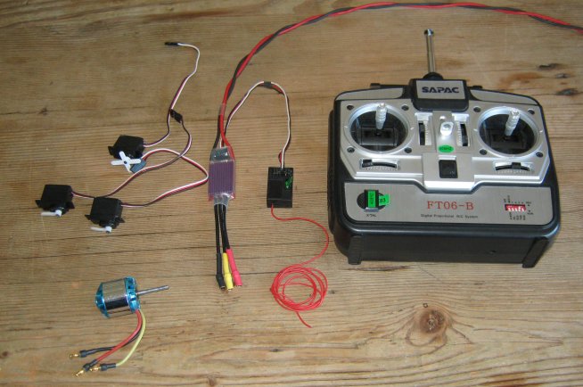
Every so often, an email is received that really should go straight in the bin rather than be opened and drooled over - Need a new hobby ? To make matters worse, I had already bought a load of R/C gear from a kid at a local Garage Sale for $5. The gear came out of a (crashed) polystyrene model aircraft and it soon became apparent that all of the electronics worked just fine. The kid in question looked quite surprised when I returned and gave him an extra $20.
I have tried to keep this page in chronological order so you can get a flavour of how the project progressed.
Characteristics
It seemed a prudent move to understand more about the R/C gear in hand before spending too much more time or money on this project.
The rule of (electrical) power transfer states "maximum power transfer from a power supply to an external device occurs when the impedance of the external device matches that of the source". The same applies mechanically where the power source is a motor and the load is a propellor. A means was therefore required to try and find the optimum prop that any given motor could drive. There was also a desire to see if DC input to the Electronic Speed Controller (ESC) affected efficiency to any degree.
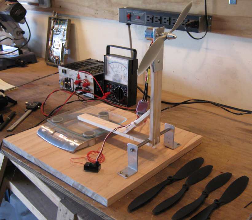
A few propellors were purchased from the local store and a suitable test fixture was constructed. Given the complete lack of previous experience with brushless motors, propellors etc. this fixture provided quite useful data. In summary, the motor had 12 poles (counted with the help of a loupe), the efficiency of the system was higher when running at 13.8V that at any lower voltage (about a 20% variation) and the available 1045 props appeared to be a good match.
With a 13.8V, 25A bench power supply, and the system being pushed hard, one motor/prop combination produced almost 600g of force. This would translate to 2.4kg thrust for four units. Current input at the point was almost 10A which is unreasonably high, but an interesting point of reference never the less.
A further test was to try various DC input voltages and adjust the prop speed so that 200g of force was measured for each step. This confirmed that 14.4V was likely the best battery voltage choice and also the inductive nature of the motor along with the switching nature of the ESCs produced a mechanism similar to a SMPSU. For most SMPSUs, with a fixed output voltage and load, input current drops as input voltage rises. There are also lower I2R losses associated with a higher voltage system since the currents will be lower.
Weight and Thrust budget
From the components in hand, a table was constructed to get some idea of expected system weight, which in turn would allow some ball park what-if fly time/battery size/battery cost calculations.
|
Item |
Qty |
Ea |
Weight (g) |
|
Motor |
4 |
52 |
208 |
|
Props |
4 |
6 |
24 |
|
Plates |
2 |
15 |
30 |
|
Tubing |
4 |
10 |
40 |
|
Collets |
4 |
4 |
16 |
|
Nuts, bolts |
20 |
2 |
40 |
|
Controller |
1 |
43 |
43 |
|
40MHz RX |
1 |
15 |
15 |
|
ESC |
4 |
22 |
88 |
|
Wiring |
4 |
10 |
40 |
|
Payload |
1 |
200 |
200 |
|
Total |
744 |
||
|
Thrust, per motor |
0.25 |
744 |
186 |
Initial purchase
About four weeks were spent looking at similar projects trying to ascerrtain common components and figuring out suitable suppliers. Philosphy revolved around "build something quickly and cheaply". This would allow me to make lots of low cost mistakes and learn as much as possible.
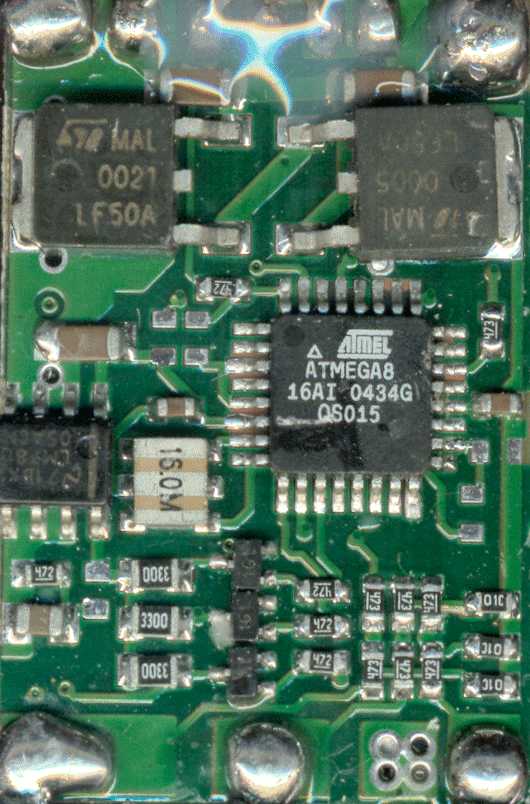
The largest cost saving was to be had by buying directly from Hong Kong, but this had risks associated with quality, amongst other things. So hand on heart, an order for US$149 was placed for 5 x 1k brushless motors, 5 ESCs (speed controllers), 30 x 3.6mm high current connector pairs, an 850k motor and an 1300k motor (just incase I had ordered the wrong motor size). Everthing arrived as expected, I took one of the ESCs apart and photographed construction (which was pretty good), and to my delight discovered that the unit used an ATmega8 - this could be (easily?) re-programmed later if required.
Performance at 14.4V
The next step was to run up the components from Hong Kong, and see how they perform. Components involved included the RC Timer BL-2830/11 Motor, Maxx EPP-1045 prop and RC Timer 30A ESC. The same fixture was used as before, and this table is for a single motor, ESC & prop.
|
I (A) |
Power (W) |
F (g) |
F / I |
|
1.00 |
14 |
87 |
87 |
|
1.50 |
22 |
138 |
92 |
|
2.00 |
29 |
199 |
100 |
|
2.50 |
36 |
249 |
100 |
|
3.00 |
43 |
309 |
103 |
|
3.50 |
50 |
330 |
94 |
|
4.00 |
58 |
370 |
93 |
|
4.50 |
65 |
408 |
91 |
|
5.00 |
72 |
442 |
88 |
|
5.50 |
79 |
460 |
84 |
|
6.00 |
86 |
492 |
82 |
|
6.50 |
94 |
502 |
77 |
|
7.00 |
101 |
529 |
76 |
|
8.00 |
115 |
560 |
70 |
|
9.00 |
130 |
630 |
70 |
Table and graph are included here. The F/I entry is an efficiency index - more is better. This setup if best run between about 1.5 and 4.5 Amps at 14.4V.
Now that the lift system is understood, it should be possible to figure out Dollars vs Flight time for various capacity, chemistry and weight batteries.
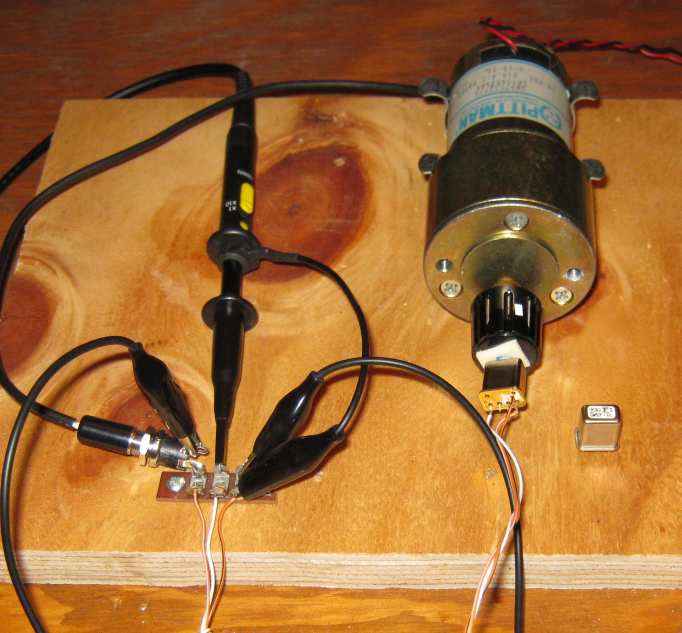
Load and Lift fixture
Test controller and Firmware
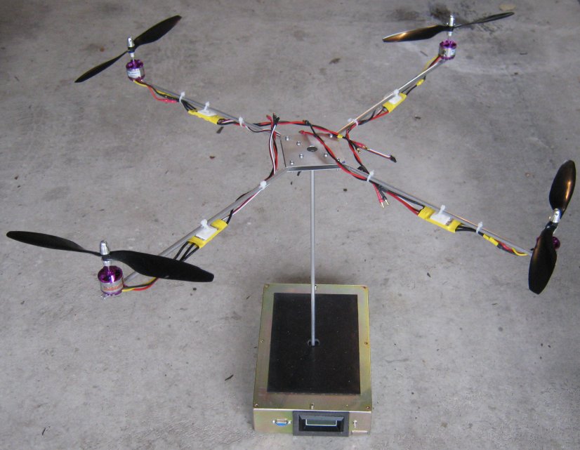
Some simple firmware was built that took CH3 from the transmitter and used it as collective motor speed. CH2 (left, right) and CH4 (up, down) were scaled in the range 70..130% and applied to collective speed before being used to control each of the four motors. The result is that as the LR/UD joystick moves, it shifts a percentage of power between each of the four motors.
Gyro testing
As part of the early experiments, it was decided to build Load and Lift Fixture. The base weight 5kg (more than any anticipated lift requirement) and contains a +-15kg load cell and associated signal processing to allow direct display of load or lift with a resolution (and hopefully accuracy) of 10 grams. Calibration is set for 1kg load and 5kg lift. The attachment shaft is 6.3mm ali tubing that has been tapped so a platform may be screwed to it's top. Top and bottom sections of this stay will be coupled using a stiff flexible hose and some hose clips to allow the unit under test to sway without stressing any measurement components.
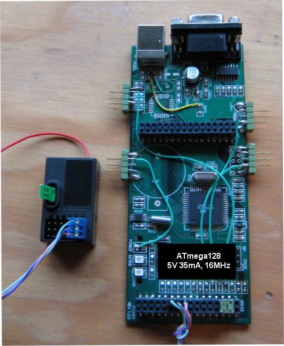
A discarded prototype controller board was available that I had designed many years ago. It contained an Atmel ATmega128 running at 16MHz, along with interface to ISP programmer and RS232 level shifters and associated DB9. The 40MHz R/C RX was modifed to feed the un-decoded PPM timing out of channel 6. This signal was used to fire Input Capture 1 associated with Timer 1. Timer 1 is a 16 bit counter that free runs at 2MHz and has terminal count set to 20ms by Output Compare 1A. A simple interrupt routine was used to measure each of the incoming six channels (and the gap). These values were passed by way of an S16 array to the foreground task for processing. Timer 1 and 3 were also set in fast 16 bit PWM mode (in association with Ouput Compare registers), so it was possible to synthesize the 1.0ms..2.0ms pulses required to drive the ESCs.
here is a short video.
A friend lent me some Fujitsu gyros which appear to happily run at 3.3 or 5V. Each was attached to the Gyro Test Fixture and the following results were noted:
|
Fujisu 10K and 3Z gyros, 5V DC, 4mA |
||
|
Sec per Rev |
4 |
|
|
RPM |
15 |
|
|
Rev per sec |
0.25 |
|
|
Delta |
2 |
Volts |
|
Sensitivity |
45 |
degrees, per second, per volt |
Battery selection
There will be some trade offs between system weight, lift capability and battery run time. The larger the battery, the longer the run time, but the higher the overall weight. The guestimate table above will be very useful to start this itereative selection process. Assuming that the battery is going to be in the region of 500g, overall lift will need to be in the order of 1300g, so each motor will need to develop around 325g of thrust. Working backwards with the thrust measurement fixture it should be possible to guestimate required current at 14.4V.
After further work, it appears that differences in battery weight does not appear to have quite such a significant affect on run time as I expected. Current plan is to go with a 14.4V LiPo battery with a capacity between 2000 and 4000mAH. eBay appears to have several vendors out of China who can supply these sorts of capacity for less than NZ$100 and am hoping for 10-15 mins flying per charge.
Suppliers
ESC, Motors, Tubing, Props, Fastners, Batteries
Mark Atherton,
October 2009, Christchurch, New Zealand