Background
This article documents the development of a micro Base Station (BS)
capable of fully controlling an analogue cellular phone (Mobile
Station)
by synthesizing all required control bit streams. It also responds to messages
from the MS as well as processed audio, thus allowing full duplex communication
between BS and MS.
Unlike the real world of the Telco with many subscribers and cell towers, this project was more focused on the minimum technology required to connect to a single Mobile Station. Moreover, it was possible to allow the Base Station transmitter and receiver to be used for Paging Channel as well as Voice Channel duties, further cutting down on hardware.
Motivation
Curiosity has been the single strongest driving force for this project
as I have had little or no exposure to Telco signaling methods or protocols.
The AMPS system, while rather old and in it's closing phase of international
use, is still sufficiently complex as to provide an interesting challenge
to a determined newcomer. This project has required an understanding of
systems design, along with analog and digital signal processing, component
level analogue, digital and software design. There is also the matter of
the design of a complete and reliable full duplex RF chain. All of this
needs to be done on a shoestring (otherwise my poor suffering wife will
complain) and in an expeditious manner (otherwise the project will remain
a dream). Bound together, these constraints have lead to quite an interesting
project.
The bulk of the work has consumed around sixteen weeks of experimentation and refinement, and has resulted in the development of around 3000 lines of C. Also, a flexible multi-processor platform has been developed supporting all required interfaces, including RF control and frequency programming. The project is far from complete but one needs to bear in mind that this is an educational project, not an attempt to overthrow the local wireless Telco ! Range and RF power is sufficiently low as being unlikely to cause any issues to adjacent services.
Motivation to prepare this article has been a mix of desire to do a brain dump of the project before I forget how it was tackled, also several friends have encouraged me to put together a possible article so they can see what I have been up to. Content has largely been guided by everything I would have liked to have known before starting the project in one place, in an reasonably digestible format.
It's also worth mentioning that total expenditure for the project has been lees than NZ$500, almost everything was acquired second hand, off of a New Zealand online auction house.
The End of an Era
Developed by Bell Telephone Labs (BTL), the Advanced Mobile Phone Service
(AMPS) was the first commercially viable and widely used cellular phone
system. First deployed in the USA during the mid 80s, it quickly gained
wide acceptance. Meteoric growth of the system enabled steady reductions
of cost of ownership to the end user due to the enormous number of units
being manufactured.
31st March 2007 in New Zealand marked the end of the AMPS network along with the slightly more advanced Time Division Multiplex (TDMA aka DAMPS) services. With all of these mobile phones kicking around, surely something useful, or at least interesting could be done with some of them...
Note: 'Forward Control Channel', 'Control Channel' and 'Paging Channel' are used interchangeably within this article.
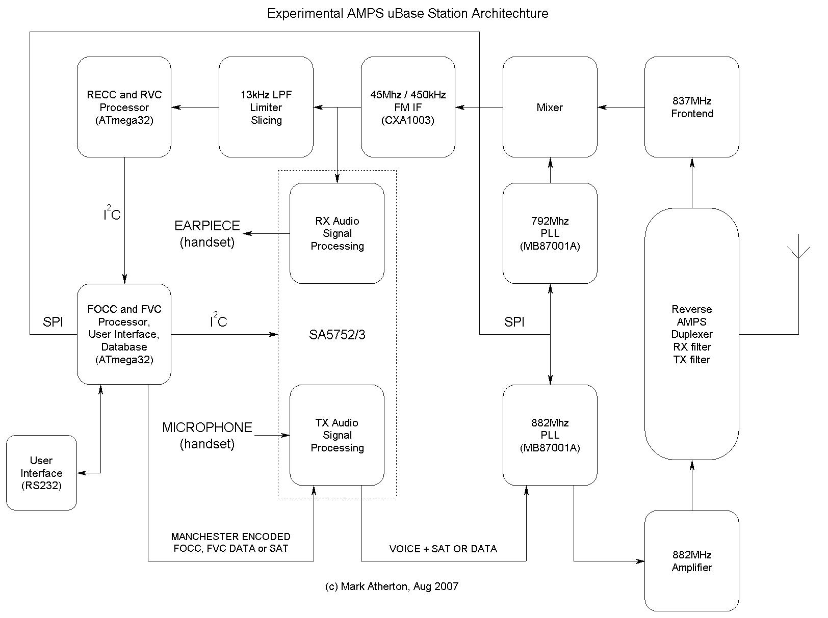
Architecture of the uBase Station
The system is a complete Analogue, Digital, RF, uProcessor, Software
hybrid, here is a composite functional drawing:
Forward Channel Processor
Main processing and control for the system is co-ordinated by the Forward
Channel Processor (FCP), this is an Atmega32 running at 20Mhz. The FCP
sets transmit and receive frequency over a bit bashed SPI channel which
controls a pair of MB87001A PLLs. Control of the audio paths and associated
gains is managed over an I2C channel to the SA5752/3 chipset. This I2C
channel also connects to the Reverse Channel Processor to allow the receipt
of reverse channel messages from the MS.
The FCP also has a single digital output that is filtered and forms part of the audio system. In Paging Mode, this channel contains Manchester Encoded FOCC data, in Voice Mode, SAT is generated by this pin.
The User interacts with the system over a 9600 baud RS232 channel and is presented with a simple terminal session allowing such options as displaying database contents, placing a Base Originated Call and displaying status when receiving a Mobile originated Call. Other UI features allow changing of default Paging and Voice channels.
Reverse Channel Processor
Audio from the Sony CXA1003 FM IF chip is first bandwidth limited using
a linear phase, 4 pole LPF,
with a cutoff around 20kHz. The data is then sliced and fed into the Reverse
Channel Processor (RCP). This is also an Atmega32 running at 20Mhz. The
RCP does full Manchester decoding, checks parity and passes valid messages
into an internal queue that is available for inspection by the FCP over
the I2C channel. Not shown, this uP also has a full RS232 interface that
allows internal states to be shown during debug sessions using a terminal.
RF system
The system is based on an obsolete Car Phone. It took quite a number
of blind purchases of 1990 vintage mobiles before a particular manufacturer
was found who used sufficiently low density components that there was a
remote chance of (for example) re-building the VCO / PLL modules so they
could operate at least 45MHz away from their designed frequency.
The TX PLL needed a 45Mhz shift from 835 up to 880Mhz. The RX VCO in it's original configuration was high side injection (925Mhz) and had to be moved to low side, so this had to move to (835 45) = 790Mhz.
The Duplexer was simply unsoldered, the mounting lugs splayed out, a central mounting hole was moved 4mm then the whole assembly soldered back into the PCB - backwards, with TX and RX ports swapped.
The RX behaves well on it's new frequency, down to around 115dBm without any adjustment. The power pin on the Hybrid Stripline PA has been set to 0V to allow only minimal TX RF power leakage (giving about 10 metres range).
Voice Processing
In my initial rush, I underestimated the importance of the 2:1 compressor,
pre emphasis and associated deviation limiter for Transmit (and complementary
signal processing functions for Receive). The first attempt was built using
some quad bilateral switches and a couple of op-amps with appropriate pre-emphasis
and de-emphasis. This circuit worked well enough to confirm that the overall
project was heading in the correct direction, but was nowhere good enough
for the prototype.
Attempt two involved hacksawing(!) out the SA5752/3 chipset, associated PCB and components from a Philips FIZZ MS. This tiny sub-assembly was mounted on a DIP plug for mechanical rigidity and ease of access for testing. The SA5753 has an I2C interface that took a couple of days poking at before I managed to program all of the 9 control registers so the device worked as expected.
User Interface screen
The chosen User Interface for this project is a simple terminal session,
realized through and RS232 connection to a Terminal emulator (TerraTerm
etc.). A very simple character based interface has been built, allowing
the user to select and change parameters such SID, dump the current registration
database and originate a call (using one of the database entries as the
source of required data to place the call). The power up welcome screen
also displays current system setting such as default Paging Channel and
default Voice Channel. All system parameters (and the whole of the user
database) are held in non-volatile memory, so the system will return to
previous settings when power is removed from the unit.
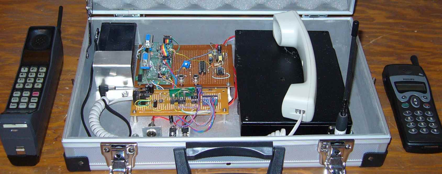
The finished, working prototype
Here are some photos of the finished prototype, installed in a small
attaché case along with a 12V battery, for the man who though he
already had everything...
Overall view, with a couple of 'appropriate' Mobile Stations.
A close up of the signal processing.
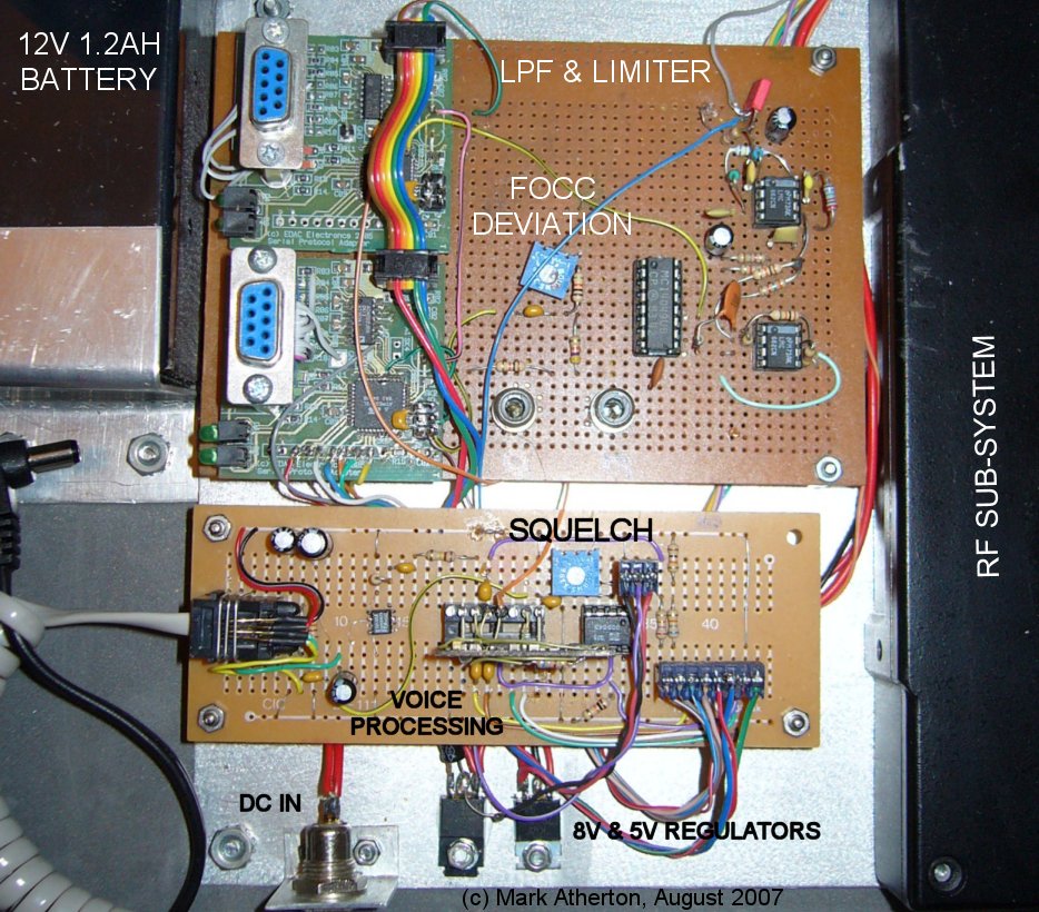
Hook up an RS232, 9600 baud terminal to the top DB9, and you will see:
Also, a peek inside the RF subsystem enclosure.

The Development Process
This project started with an unexpected win of a piece of test gear
from an online auction house. Many pieces of incidental test software,
test hardware and RF test fixtures were required to understand and appreciate
some of the nuances of the AMPS system. One of the recurring themes was
re-usability of test hardware, so complete new fixtures could be created
by dropping in appropriate firmware.
Commercial Test Gear
December 9th, 2006 and I won a broken Wavetek 3600D Cellular Test
System on the NZ auction house, TradeMe. It arrived, and the first thought
to enter my head was I wonder what it does, second was wonder if I can
fix it. The main problem was apparently a partially illuminated LCD. Four
hours of fiddling later and the voltage regulator had been replaced and
the LCD was back up to full steam. The only apparent other problem was
a busted 3.5 floppy drive, which was straightforward to replace.
The 3600D was something quite unlike any piece of test gear I have previously used, owned or experimented with. It provides a high level of automation to allow Analogue phones to be tested and repaired, but more useful to me, a complete synthesis of signals broadcast by the Telcos from their Cellular towers.
Attaching a Motorola Bag Phone to the test port of the 3600D and digging through various menus resulted in the phone being registered. Basically the phone handed over it's Electronic Serial Number, Phone Number and it's capabilities. The 3600D can then offer tests relevant to the phone in question. It's not possible to send or receive audio from a MS until the 3600D has it registered. Even this simple and obvious requirement was new to me so I had many hours ahead of me fiddling with various settings and seeing how the attached mobile responded.
The Reference Documents, IS-136-xxx
One of the first unknowns posed by the 3600D was Protocol selection;
IS54 or IS136 ? No idea, not a clue, never heard of either. IS-136 was
obviously(?) the more recently signed as they both are from the same standard
organization and is numerically higher.
A great deal of searching uncovered a complete stash of the standards document (on an FTP site) which appears to run to 122 PDF documents, about 355MB total. I am guessing that this set runs to about 1000 pages; quite a bit of bedtime reading.
Many hours of reading and skimming reduced the essential reading to IS136-127, IS136-140 and IS136-150. The latter two being the bulk of relevant standard.
Modified Scanner, the AR-3000
The next phase of the project was to start gathering data off air (out
of the 3600D) for analysis. The 3600D provides as plentiful supply of modulated
data and an AOR AR-3000 was put into service as the demodulator (initially
in Wide band FM mode, until a 30kHz bandwidth NBFM IF filter could be installed).
The demodulator output was also brought out directly which was used to
feed various pieces of home made test equipment (see later).
The scanner was then programmed for the four mains service channels:
|
|
|
|
|
|
|
|
|
|
|
|
|
|
|
|
|
|
|
|
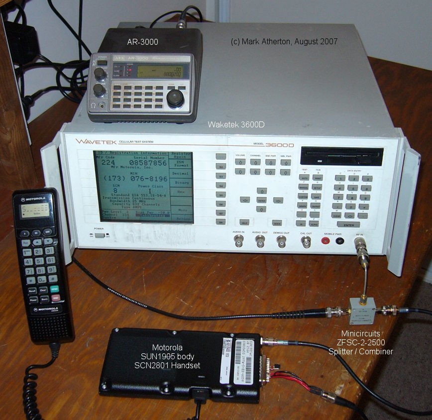
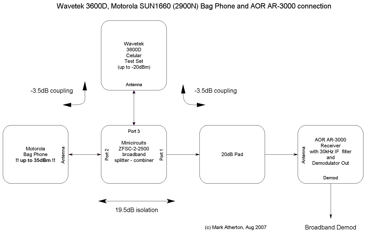
Test Configuration
One of the problems with trying to received bit streams from the 3600D
was that a mobile phone also had to be attached to the same port. Hence
the opportunity of blowing the RX front end up the first time the mobile
goes to transmit. Part of the RX protection was an always-inline 20dB attenuator,
the second part was the use of a ZFSC-2-2500 broadband splitter.
On the ZFSC-2-2500, Port 1 connects to the AR-3000, Port 2 to the mobile (Motorola Bag Phone) and Port 3 to the 3600D. Minicircuits claim > 19dB isolation between Port 1 and 2. Even with Class 1 mobile set to full belt (3W, +35dBm), the AR-3000 will only ever see -7dBm which will probably not cause any damage. The 3600D is only capable of generating 23dBm at 880MHz, so that is also well below any damaging level.
With this setup, it was possible to easily receive data from either the Wavecom 3600D Test Generator on Forward Control Channel 334 (880.02MHz) or the Mobile on Reverse Control Channel 334 (835.02MHz).
The modified Motorola Bag Phone, SUN1660
The Motorola SUN1660 is a sufficiently old unit that it is reasonably
easy to dismantle and to probe. The newer units such as the SUN1905 are
much higher density construction, and use much higher integrated subsystems.
If it was possible to inject FOCC data directly into a MS rather than have
to go via RF modulation, that would cut out a large number of unknowns
and could be a useful piece of test kit.
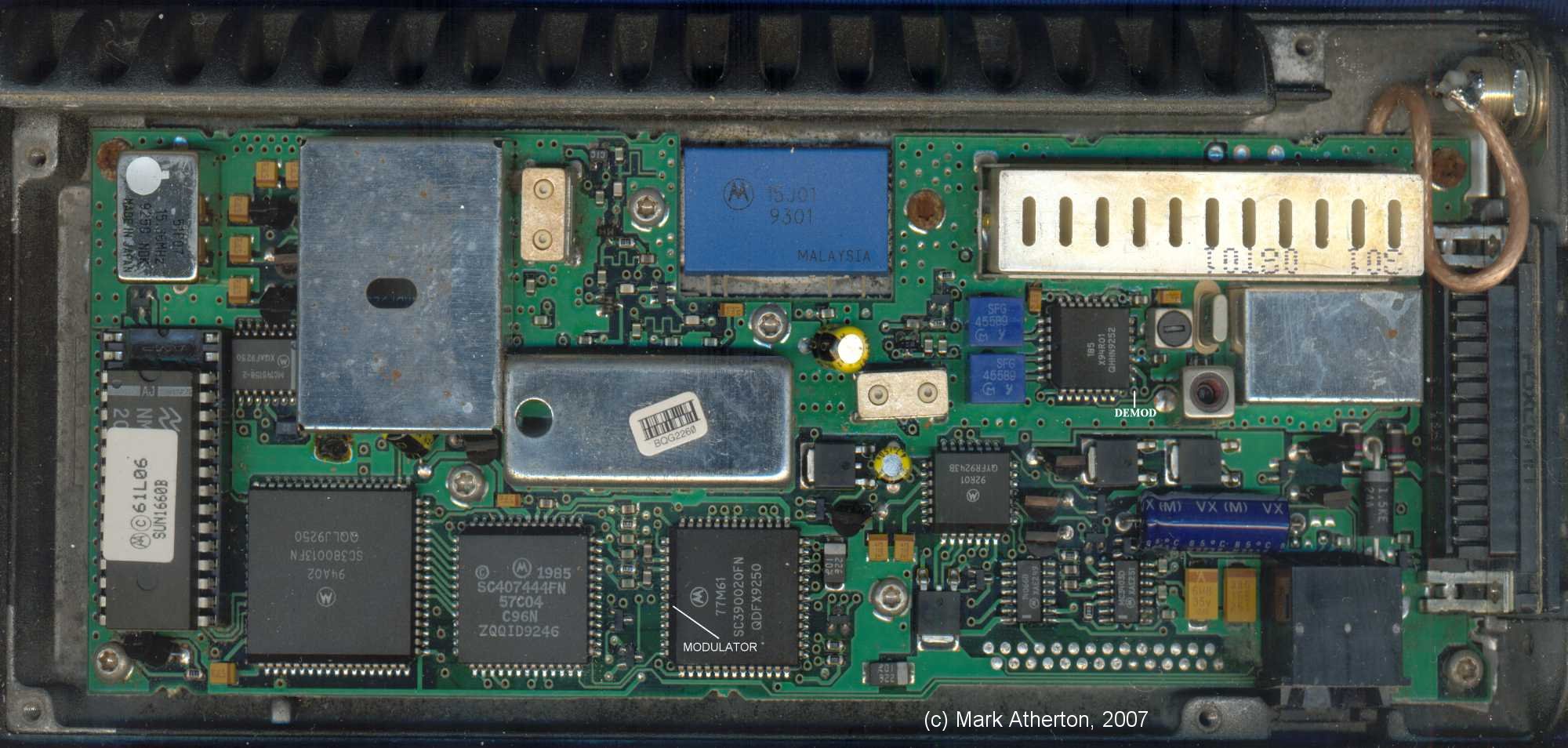
As with most Motorola MS products, the majority of the LSI is proprietary and house marked. By setting the 3600D to generate a FOCC channel (which is its idle state) and connecting the 3600D RF port to the Motorola antenna connection, it was easy to locate the FM demodulator output by probing around for what looked like appropriate data. Pin 18 of the 94R01 appeared to have a valid signal on it. This could then serve as either a reference demodulator, or by installing a switch and feeding data in via a small capacitor, it could serve as a data decoder, with status indicated on the SCN 2xxx handset (no signal, roaming etc.)
The MS was also expected to occasionally respond to messages from the BS (registration, acknowledgments to commands etc). To find the output from the data modulator, a call was set up between the SUN1660 and the 3600D, then the 3600D was programmed to send a sequence of power up/down messages (changing between PL6 and PL7). It was reasonably easy to locate the RECC message drive to the modulator which his on the 77M61, pin 53 (of a 54 pin PLCC).
Also, Mike Larson compiled a rather useful document; The Motorola Bible which is an interesting collection of things-to-do-with-your-bag-phone. By placing one of these units in Test Mode (ground pin 21 of the DB25) a whole slew of new capabilities and features becomes available.
Data Capture
One of the first pieces of test equipment to aid with the analysis
of the Manchester encoded data was a Hard Disk Audio Recorder. This allowed
sections of data to be inspected and played back for analysis. Data had
to be recorded as raw PCM since any form of lossy compression (like MP3)
will cause significant phase errors etc. which is unacceptable.
Soundforge XP 4.5 was to hand, which with the available (on motherboard) soundcard was capable of capturing 16 bit linear PCM at 96kHz sample rate. Setting input and output gain and mixer options (using XP volume control panel) initially caused complete corruption of the data. Selecting only linein and lineout as available devices resolved the issue.
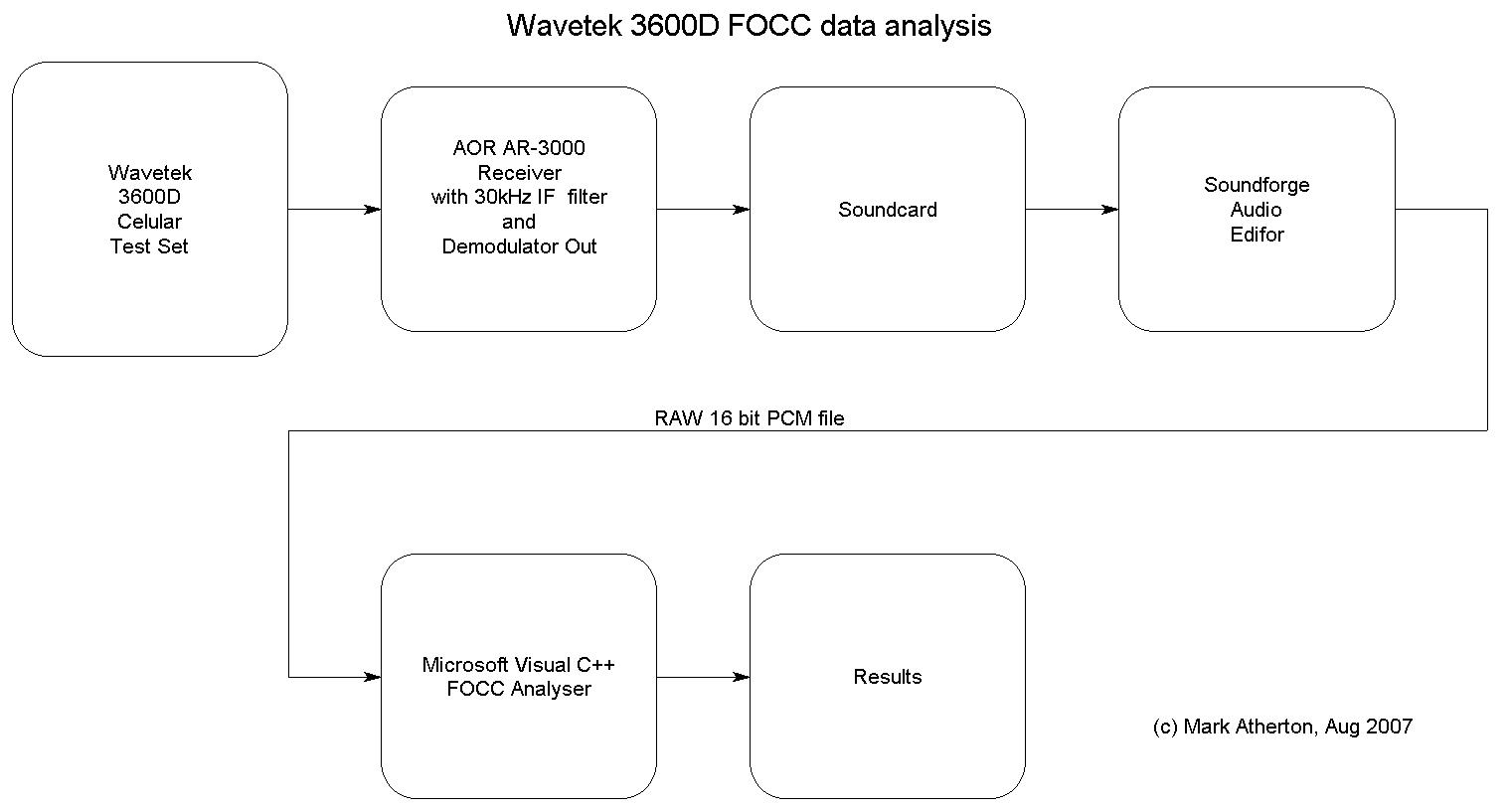
First steps towards bit stream analysis
The first steps towards analysis of the FOCC channel involved capturing
the demodulated RF from the demod output of the AOR-AR3000 using a soundcard
running at 96kHz. The audio (data) was then saved as an 8 bit mono
PCM (RAW) file.
First test was to check PC sample rate clock vs incoming data clock was as expected. Input data was loaded into a 5k byte buffer and hard limited. The number of samples between rising edges was then counted. Given that Fs = 96kHz (10.4us) a distribution buffer as created with 16 entries. This gave measurement bins from [0..10] thro [156..166]us in 10.4us increments.
Results were as follows: 0 0 0 8 219 261 36 0 2 59 145 52 0 0 0 0
As expected, there were two peaks around bins [4..5] and [9..10]. This indicates a wide eye pattern.
Initially, data was hand processed so that the software could assume that Dotting (1,0,1,0..) was present at the start of the PCM buffer. The software then starts the decode process by searching for a ve transition then a +ve transition. Given the nature of Manchester encoded data, this +ve transition point is now going to be mid way between clocks so the sample pointer is moved to the next sample point by adding roughly half a data cell (5 samples). The pointer is now at the correct sample point in the data and it is a matter of sampling data every (96/10) bytes in the buffer. Rounding naturally occurs due to the integer arithmetic. Here are the results of early analysis:
VC6 analyzer
Recorded from AR-3000, WBFM, 835.050MHz
Reg initiated by Wavetek 3600D, Data from Motorola Bag Phone
Distr 0 0 0 8 219 261 36 0 2 59 145 52 0 0 0 0
010101010101010101010101010 11100010010 0000000 Dotting sync DCC
10101110 1000 111001101110100111011111 111110100000
10101110 1000 111001101110100111011111 111110100000
10101110 1000 111001101110100111011111 111110100000
10101110 1000 111001101110100111011111 111110100000
10101110 1000 111001101110100111011111 111110100000
0001 00000011 011010000000000110101101 001110101011
0001 00000011 011010000000000110101101 001110101011
0001 00000011 011010000000000110101101 001110101011
0001 00000011 011010000000000110101101 001110101011
0001 00000011 01101000000
Decoder has 5k PCM buffer, 8 bits, 96kHz sample rate
These results have been hand annotated to split data fields into a more readable form, but data is verbatim per capture and Manchester decoding.
A lot of hand entry of bit patterns into spreadsheets followed this part of the project to confirm that data was expected. Also, continuous thumbing back and forth through the IS-136-xxx specs to find how to decode the appropriate messages.
Real Time Manchester Decoding
A small Atmel Atmega32 was available as a readily programmable test
platform in the move towards real time analysis and capture. Several algorithms
were attempted in the process of decoding the Manchester data stream. Attempt
one was petty much as described above in the off-line analysis. Edges were
identified and a sample clock maneuvered until it was placed correctly
to sample the data. Various shortcoming of the Atmel timer and interrupt
architecture made context switching (between sync acquisition and data
sampling) a nightmare. It sort of worked, but attempting to justify deterministic
behavior was a complete headache.
Second approach was a hybrid analog/digital solution. From the clock datum, the data will follow one of two patterns; low for half a data cell then high, or high for half a data cell then low. By doing a real time correlation between the incoming data and a locally (I and Q) representation of the data, it should be possible to sample the integrator at the end of the sample period. When correctly phased, the integration of (DATA XOR Q) should approach 0 while (DATA XOR I) should approach |1|. The polarity of the (DATA XOR I) indicated data value (1 for 0 and +1 for 1). The balancing act is to keep the Q channel product approaching 0, which requires an appropriate control loop. The beauty of this system is huge amount of noise immunity afforded by the integrator.
Finally, a pulse width measurement system was constructed. This intent being that provided it was preceded by a suitable low pass filter (20kHz), there should not be too much of an issue with noise. This was originally implemented as a stop-gap measure, but has been tweaked to the point that performance appears to be fine for this project.
Real Time Data Capture
The next goal was to build a real time system that could decode Manchester
data, and provided parity was checked OK and wasn't a repeat, is placed
in the top end of a FIFO. This sounds like a simple thing to do, however
when everything is coded in C, data is rattling in every 50-100us and there
is only a 20MHz 8 bit micro to hand, some compromises have to be made.
The main comprise was to reduce the capability of the BCH (40:28:5) error management system from one capable of 2 bit error correction down to data accept or discard based on parity OK.
Even accepting this reduction of performance, many long hours were spent building and testing sub-systems prior to integration. As with the whole project, the effort generally went into 60% design, building and discarding x86 prototypes, 30% real time coding (once the real problem was understood) and 10% integration and test. The latter phase generally just dropped in and more or less worked first time.
FOCC - Real Time Data Analysis
This was probably the first really rewarding part of the project, because
a ready supply of FOCC data was available (either from the 3600D or live
data care of Telecom NZ). It didn't take too much effort to write a half
reasonable FOCC data dissembler (again, designed and de-bugged on an x86).
Many measurements were possible including distribution of packet types,
figuring out Telecom NZs re-registration scheme (every 20 mins), along
with system configuration used by both my test gear and the local telco.
Here is a sample, with annotation. Data has been limited to fields with Number of Additional Word Coming (NAWC) greater than 1:
Philips FIZZ Mobile attached to Wavecom 3600D
Mobile details:
Mfg/Model
Philips FIZZ
ESN 0xE403B66B 228 00243307
MIN2 0x1AD
(530)
## 530 and 173 are the AMPS country codes for New Zealand ##
MIN1 0x029C6C 121-7219
SCM 0xE
14, Power Class III, 832 channels, Discontinuous
Standard
EIA533, IS-54A
FOCC channel data with Overhead Data (OHD):
FOCC C00A29E0
OHD 6 Word 1 Param
DCC 0
SID1 28
EP 1 Extended protocol (Digital available
?)
AUTH 0 Authentication method
PCI 1 Base can assign Digital traffic channels
NAWC 3 Number of additional word coming = 3
FOCC CF299470
OHD 7 Word 2 Param
DCC 0
S 1 Send ESN
E 1 Extended Address Field
REGH 1 Registration for Home stations
REGR 1 Registration for Roaming stations
DXT 0 Discontinuous Transmission Field
N-1 14 0x14+1 = 21.
RCF 1 Read Control Filler (CF has data
atten level ?)
CMPA 1 Combined Paging Access
CMAX-1 14 Number of access channels in the system =
21
END 0 Not End
FOCC CF03E800
OHD 0 Reg Ident
DCC 0
Reg ID 3E8 REGID
END 0 Not End
FOCC C20010C0
OHD 4 Global Action
DCC 0
ACT 2 Registration Increment Global Action
Message
PAYLOAD 10 RGINC 0x001, RSVD 0000
END 1 End
All of this data, when read in conjunction with the IS-136-140B surprisingly starts to make sense. At this point in the project, the main question really is what is the Paging Channel and what data does it carry. When usage and payload have been ascertained, that is a very useful starting point to work on the foundations of synthesizing the required data stream.
Summary of the Four data channels
FOCC - (Paging Channel). This contains two payloads A and B. The A
payload is listened for by MS with even phone numbers, and the B payload
is listened for by MS with odd phone numbers. The A and B words are 40
bits long, encoded BCH(40,28;5) so each word contains 28 bits of corrected
data. Word A is repeated 5 times as is Word B
From the foundations laid down by the work involved with the development of the FOCC (Paging Channel) analyzer, it was a reasonably small step to create similar analyzers for the other three channels:
RECC Reverse Control Channel. Data sent from the MS back to the BS before the channel change to the Voice Channel. This carries Registration and MS capability information, amongst other data. This is a variable length message (but usually 3 or less words). Each word is 48 bits, comprising 36 bits data + 12 bits parity and parity is computed using BCH(48,36;5) and each word is repeated 5 times.
FVC Forward Voice Channel. Once the MS has been allocated and has moved to a Voice Channel, the BS needs to control Power level of the MS and also (for a real system) pass new channel change information over when Handoff from one cell tower to another occurs. As with FOCC, this channel uses 40 bit long message words, encoded BCH(40,28;5) so each word contains 28 bits of corrected data and 12 bits of parity.
RVC Reverse Voice Channel. This is mainly used to send FVC acknowledgments form the MS back to the BS. As with RECC, each word is 48 bits long, comprising 36 bits data + 12 bits parity and parity is computed using BCH(48,36;5).
The Four Analyzers
From the general work done developing the FOCC analyzer, the same software
design structure has been used for each of the three other analyzers. The
main task is to demodulate the bit stream, search for Dotting then Sync,
frame the data appropriately, check parity and push non repeating words
down a wide FIFO to the foreground task. This approach completely decouples
the development work required by the main task loop from any real time
activities.
By sharing a common microprocessor hardware base, swapping between analyzer types is just a matter of loading different firmware. This is a time when names and versions of each analyzer type are conspicuously displayed on the User Interface. I have had several times when an analyzer has not been responding as expected, to discover that the terminal was plugging into the wrong device, or the correct device had wrong firmware loaded
Philips Semiconductors have a concise summary of the four signalling formats in their UMA1002 Datasheet.
Synthesis and Delivery of the Paging Channel
With the ability to decode and disassemble the Paging Channel, the
associated payload was becoming better understood. Several hurdles had
to be overcome before the paging channel could be synthesized:
1) How to validate correct delivery of a synthesized Paging Channel
?
The only visible indication that a MS is attached to a valid Paging
Channel is that the No Service indicator is extinguished. Further than
that, if it were possible to change the System Identifier (SID) on the
fly, the Roam indicator could also be controlled. So the first, low hurdle
target was to control No Service and Roam on a MS.
2) What is the easiest way to deliver the payload ?
The over the air interface is normally used to deliver the Paging
channel to a MS. This adds a whole new level of excitement and uncertainty
to the project when the modulation characteristics for the RF sub-system
have yet to be defined, let alone built. A more direct approach towards
delivering payload was needed.
The earlier generation of Motorola bag phones (SUN1660) were build using low density ICs (PLCC, rather that than high density Gull Wing/Quad Flat Pack parts used in later models like the SUN1905). By intercepting data from the FM demodulator (Pin 18 of the 94R01, see previous comments on the subject), its should be possible to inject data directly rather than use the Air Interface.
3) What is the minimum acceptable payload to do something useful ?
Three packet types appeared to require complete understanding:
OHD System Word 1 (see IS-136-140B page 63), important elements include Digital Color Code (DCC), System Identifier (SID) and Number of Additional Words Coming (NAWC)
OHD System Word 2 (see IS-136-140B page 64), important elements include Home and Roam registration enable bits (REGH and REGR), number of paging channels in the system (N-1) and the Read Control Filler (RCF) bits.
Control Filler (CF) (see IS-136-140B page 72). This is the idle data that is multiplexed into Paging Channel when no other data needs broadcasting.
For the early attempts at Paging Channel synthesis, appropriate values for these three words were decoded from the Wavecom 3600D. These were know good data and appeared to be a minimum useful dataset. This was also a useful approach since the associated 12 bits of parity could be taken verbatim rather than having to be generated and validated.
The Busy/Idle bit needed to decided upon and the 1 value was chosen, this indicates that the Reverse Channel (RECC) is always available.
Finally, a real time multiplexer had to be created in software whose job was to create a continuous stream of 463 bit frames of Control Filler, injecting OHD Word 1 and OHD Word 2 every 800ms. Currently the system can generate different A and B payloads (destined for odd and even phone-numbered MS).
Following the multiplexer was the Manchester Modulator. Since Manchester data is polarity sensitive, it should be possible to compile the modulator with both polarities of data available.
Debug of synthesized Paging Channel
The multiplexer was probably the most difficult part of the prototype
software to write and debug. As before, a huge effort went into the design
of the system, with significantly less effort involved with coding, testing
and integration.
Since the FOCC analysis system had already been built and had been used to analyze the output of the Wavecom 3600D, it was connected back-to-back with the new synthesis system and was used to fix the few subtle problems that lurked in the first incarnation.
Injecting data directly into the SUN1660 yielded the expected results. Service was indicated as being available and changing OHD Word 1 with different SID values took control of the Roam Indicator.
Summary of the AMPS system and the uBase Station
Much has already been written on the workings of the AMPS system, and
can be readily found on the Web. Here is a potted summary:
Specification
This system has been designed around the AMPS section of the reference
documentation TIA/EIA IS-136. The most important components being IS-136-140
and IS-136-150. These two documents contain the bulk of the signaling and
protocol for this project.
Like most specification documents, they are almost indigestible when read in isolation, a background in wireless telco would also be an advantage when trying to interpret them. I had none of these advantages so I sought to explore them through the use of a piece of commercial test gear which lead to the development of many pieces of home cooked test equipment.
Modulation and Channel spacing
AMPS is a hybrid analogue/digital system based on a 30kHz channel spaced
FM service. Analogue usage is primarily to carry voice along with various
flavors of Signaling Tones (the equivalent of call progress tones in a
wireline service). Digital channels are by means of Manchester encoded
messages and are used by both the BS as well as the MS; data rate is nominally
10kbs.
One of the knock on effects that I hadn't appreciated by the use of a 30kHz channel spacing is that other parts of the system tend to be driven by multiples of this frequency such as 450kHz IF (30kHz x 15); 45MHz IF (30kHz x 1500); 106.050Mhz (30kHz x 3535); 9.6MHz System Clock etc.
Error Management
All digital messages are protected by the addition of parity information.
From the Base Station to the Mobile Station, data is aggregated into (multiple)
28 bit words and are protected with 12 bits of parity. From the Mobile
Station to the Base Station, messages are aggregated into (multiple) 36
bit words and are protected with 12 bits of parity. In both cases the parity
is generated using Bose, Ray-Chaudhuri, Hocquenghem (BCH) error correcting
code. Further assurance of correct delivery is managed by repeating the
messages several times per transmission.
Frequency plan for the 666 channel system.
The most recent incarnation uses a fragmented frequency plan of 832
channels. In an attempt to simplify the design of this system, a decision
was made to use the original 666 channel band plan which has simple linear
translation between channel and frequency.
|
|
forward |
reverse |
|
|
|
|
|
|
|
|
|
|
|
|
|
|
|
|
|
|
|
|
|
|
|
|
|
|
|
|
|
|
|
|
This is a gross simplification of the frequency plan, the salient features are that channel 400 is nominally used for voice and channel 334 is nominally used for the control / paging channel by this project.
BS TX frequency = 870 + (channel * 0.03) MHz
MS TX frequency = 825 + (channel * 0.03) MHz
To allow a normal (full duplex) conversation, Base Station and Mobile Station both transmit for the duration of the call, with a 45Mhz split.
Forward and Reverse channel naming
The signal path from the BS to the MS is referred to as the Forward
Channel. Depending upon context, this may be the Forward Control Channel
(FOCC, Channel 334 in this system) or can become the Forward Voice Channel
(FVC, channel 400 in this system).
The path from the MS to the BS is referred to as the Reverse Channel.
Same channels are used as BS to MS, but with the 45Mhz offset. These are
nominally referred to as Reverse Control Channel (RECC) and Reverse Voice
Channel (RVC).
|
|
|
|
|
|
The Paging Channel
The paging channel is the heart of the AMPS system, without it, all
MS will indicate No Service and calls will be impossible. Paging channel(s)
are set around the middle of the allocated spectrum, CH334 (880.02MHz)
being the Initial Paging Channel for this system. This channel is a continuous
data stream being a multiplex of system identification (including SID which
controls the MS Roam Indicator), BS capability (Digital service capability
etc). The channel is also used to initiate MS registration and to start
the Base Originated Calls mechanism. While the Paging Channel is idle,
the system broadcasts Filler Control packets. Every 800ms a System Overhead
(OHD) message is broadcast, this gives the channel a regular heartbeat
like sound when monitored on a scanner.
Registration
Acquisition of a new control channel by a MS forces the MS to send
registration information back to the BS. Registration includes the capabilities
of the MS, Electronic Serial Number (ESN), MIN1 (Area Code), and MIN2 (Phone
Number). Overhead Messages for the BS also force the MS to re-register
several times an hour (was every 20 minutes for NZ Telecom).
Registration Database
For this project, a small database manager has been built that stores
ESN, MIN1 and MIN2 in non-volatile memory every time a registration message
is received by the BS. If a call is to be placed by the BS, the MS to be
called is selected out of the database. A User Interface command has been
included which dumps the content for the database for inspection by the
user.
Forward Control Channel Framing
The paging channel always is configured as a Forward Control Channel
(FOCC), each frame of data comprises 463 bits. The FOCC data is split into
two payloads A and B; The A payload is destined for all MS that have
an even phone number (MIN2 LSB = 0), the B payload is destined for MS with
odd phone numbers (MIN2 LSB = 1). This provides a simple method of load
sharing for the BS when many MS are used.
Each FOCC frame starts with a Dotting sequence, this is a 10 bit 1010.. pattern and allows the decoder to ready itself for sync detection. Sync follows, which is an 11 bit Barker Code pattern, 11100010010. Following this is the 40 bit A payload and the 40 bit B payload. A and B are then repeated 4 more times. Bit count so far is therefore 421.
As part of the normal operation of the whole system, MS has to go to transmit and send messages to BS. To inhibit more than one MS occupying the reverse channel at a time (a process called reverse control channel seizure), the FOCC also includes a multiplex of Busy/Idle bits. A 1 means that RECC is idle, so any MS may send a message. A 0 means RECC is busy, so MS should not occupy the channel.
Once during the transmission of Dotting and Sync, a B/I bit is inserted. This increments the bit count per frame to 423. Every 10th bit of A and B payload, a further B/I bit is inserted, this brings the grand total up to 463 bits per frame. Given the 10kb/s data rate, each FOCC frame takes 46.3ms to transmit.
Power Level control
To conserve battery life and to minimize station to station interference,
BS and MS are equipped with a multilevel RF power control mechanism. Each
step is nominally 4dB lower than the previous. For the class of hand held
Mobile Stations used to test this project, PL7 is the lowest power, with
output around 0dBm.
Digital Color Code (DCC)
In the context of a large cellular system each cell has a value 0,
1 or 2 to identify, or more to the point to differentiate it from an adjacent
cell. DCC is a two bit value encoded in every digital message from the
BS. For use in this system, DCC0 is used and is a compiled-in constant.
Supervisory Audio Tones (SAT)
Once a voice channel has been established between BS and MS, the BS
transmits one of three SAT tones 5970, 6000 or 6030Hz. These are analogue
equivalents of the DCC identifying the cell that the BS is located in.
For use in this system, SAT0 (5970Hz - associated with DCC0) is used and
is a compiled constant.
Audio Processing
The audio chain contains a 2:1 compressor, pre emphasis and is peak
deviation limited for Transmit, de-emphasis and 2:1 expander for Receive.
There is also a 3003kHz bandpass filter. The MS will only allow voice
communication with the BS provided it is also receiving the correct SAT
for the BS, so for this system, the MS must always hear a 5970Hz tone for
the BS to unmute its audio path.
System Identifier
All MS units as purchased come pre-programmed with a Home SID. This
is a fixed 15 bit value that (amongst other uses) controls the Roam indicator
on the handset. When the MS and BS SID are the same value, the Mobile knows
that it is attached to a Home system, so the Roam indicator is not displayed.
Conversely, the Base knows that the MS it is communicating with is a member
of the same system so it will not apply roaming charges. Other bit fields
send by the MS in the Paging Channel are also used by the MS to determine
whether it is allowed to register on the current BS system or not based
on current Roam conditions.
BS Analogue Signal processing
For this project, the Philips SA5752 / SA5753 chipset was chosen to
handle BS signal processing. They provide a very simple analogue interface
between the BS handset and BS modulator while also allowing injection of
SAT when needed. It also provided all required switching between BS demodulator
and BS handset with SAT filtering. The chipset is controlled by uploading
a reasonably straightforward set of command and routing tables. These tables
set audio path switching and audio path gain. For this system there are
two main table sets: Paging Channel Profile and Voice Service Profile.
Simplified Mobile Originated Call:
For a MS originated call to be possible, the MS must be receiving a
valid control channel and must meet roaming criteria set by the BS as well
as rules programmed into the MS.
The operator of the MS dials the number to be called then the send button. The MS then asserts itself (goes to transmit) on the Reverse Control Channel and sends a Mobile Originated Call message along with the number to be dialed to the BS.
Provided the MS recognizes and can support the type of Mobile Originated Call, it send back a message to the MS stating the channel that the voice message should be conducted on along with the Initial Power Level.
BS and MS then both change frequency (in the context of this document to channel 400) and the conversation an continue until BS or MS drop carrier. There is a more formal method of call termination using a 10kHz Signalling Tone, but this hasn't been implement yet.
During the call, the BS is able to change the channel that the mobile is using (using a hand off message) and change the MS power level as appropriate to maintain a minimum system performance.
When the call has been dropped, the BS reverts back to broadcasting control channel messages on the FOCC where it waits for user intervention over the RS232 control port to initiate a Base Originated Call or until another Mobile Originated Call is received.
Credits, Notes, Large Font, Small Print etc.
I would like to thank Dr. Robert Morelos-Zaragoza for making his BCH
code public. This project quite simply would not have worked if I hadn't
had access to his source code.
Please take chunks from this article as you feel fit, but please acknowledge my work appropriately.
On my travels I also found this IEEE transcription of an interview with Joel Engel, one of the fathers of the AMPS system.
Apologies for the American spelling, mine is atrocious and I only had a US spell checker at hand.
Comments and corrections always welcome.
Regards,
Mark Atherton - markaren10@yahoo.com
August 2007, New Zealand